What is the best distance between a VFD and the motor? The honest answer depends on the drive, motor, cable, and installation environment. There is no universal distance that fits every system. A compact machine may run reliably with a 10-meter cable. Another installation may experience motor heating, insulation stress, or nuisance faults at the same length.
Dr. Thomas M. Jahns, a respected power electronics researcher, has emphasized the importance of managing voltage stress in motor-drive systems: “The details of the drive and motor interface determine practical system performance.” This principle matters in the field. A VFD creates fast voltage pulses, and long motor cables can reflect those pulses back toward the motor. The result may resemble a small electrical echo, repeatedly striking the winding insulation.
Manufacturers often publish maximum cable lengths for specific drive families. Those limits can change with cable construction, carrier frequency, grounding quality, and motor insulation. Shielded VFD cable, correct bonding, and a suitable output reactor can improve reliability. A dv/dt filter or sine-wave filter may be necessary for longer runs.
The shortest route is not always the best route. Poor cable routing beside sensitive control wiring can create noise, even over a modest distance. I have also seen specifications treated as guarantees, which is a risky assumption. Real installations include heat, dust, imperfect grounding, and aging insulation.
This guide examines practical distance limits, waveform effects, cable selection, and protection methods. It also explains when a longer cable becomes an engineering decision rather than a simple installation detail. Always confirm the final distance with the VFD and motor manufacturers.
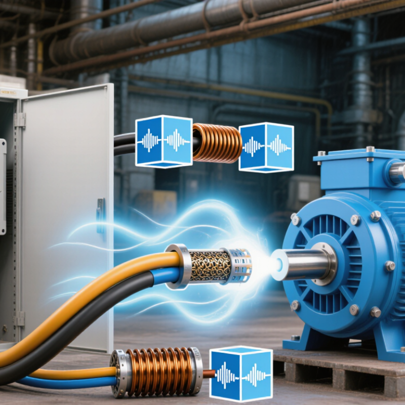
The distance between a VFD and motor can change voltage stress, heat, and reliability. Long cable runs add capacitance and impedance. They can also create reflected-wave voltage at the motor terminals. For a 460-volt motor, NEMA MG 1 Part 31 allows peak impulses up to 3.1 times rated voltage under specified conditions. That can exceed 1,400 volts. Insulation damage may begin quietly, not immediately.
Cable length is only one factor. Switching speed, cable construction, grounding, motor insulation, and installation layout also matter. IEC 61800-3:2017 emphasizes conducted emissions and installation environments, while IEEE 519-2022 addresses harmonic performance at the power system interface. Neither standard gives one universal motor-cable distance. That is the uncomfortable part. A 30-meter cable may work well in one system, yet fail in another with faster switching or poor grounding.
Tips: Check the VFD manual and motor data first. Measure the actual cable route, including vertical sections. Use symmetrical grounding and shielded VFD-rated cable where required. For long runs, consider an output reactor or dV/dt filter. Record motor-terminal voltage during commissioning, not only VFD output voltage. In practice, this measurement often reveals problems that calculations miss. Leave room for doubt. A clean installation can still produce unexpected bearing currents or nuisance trips.
How to Choose the Best Distance Between a VFD and Motor?
The distance between a VFD and motor depends on more than cable length. The VFD creates fast PWM voltage pulses, which can reflect through the cable. Longer cables increase capacitance and may cause insulation stress, motor heating, or nuisance trips. Cable impedance, conductor size, switching frequency, motor voltage, and motor insulation all affect the safe distance. A 30-meter installation may work well in one system, yet create problems in another.
Installation details matter too. Shielded, symmetrical cables can reduce electromagnetic interference. Proper grounding helps control leakage current. Keep motor cables away from sensitive signal wiring, especially near encoders or temperature sensors. Cable trays, bends, ambient temperature, and parallel motor cables also influence performance. During commissioning, measure motor current and inspect the cable route. Do not rely on distance alone. That assumption often fails.
Tips: Check the VFD and motor manuals before selecting cable length. Confirm the maximum recommended distance and required cable type. Consider an output reactor or sine-wave filter for long runs. Reduce the switching frequency when the application allows it. Keep connections tight and verify grounding at both ends. A practical test under full load is valuable. It may reveal heating that calculations miss. When conditions are unusual, ask a qualified engineer to review voltage drop, reflected-wave risk, and EMC requirements.
Choosing the best distance between a VFD and motor starts with the motor cable, not a universal distance limit. In practical installations, I have seen short cable runs create interference when ordinary power cable was used. A suitable VFD cable normally includes symmetrical phase conductors, a low-impedance shield, and a dedicated protective earth path. These features help control common-mode current and reduce bearing and control-system problems.
Distance still matters. Longer runs increase reflected-wave stress, voltage drop, and electromagnetic noise. Check the drive manufacturer’s maximum cable length, but do not treat it as a guarantee. The actual limit depends on switching frequency, motor insulation, cable capacitance, grounding, and enclosure layout. For longer routes, use a cable designed for inverter duty and verify shield termination at both ends according to the installation design. Avoid loose pigtails. They raise impedance.
I once treated cable length as the main design variable. That was too simple. A better check includes measured insulation condition, motor frame bonding, and separation from signal wiring. Keep the motor cable away from encoder and communication cables where possible. If the run approaches the permitted limit, consider an output reactor or dv/dt filter, then confirm the result with voltage and current measurements. Field judgment matters, and I would document every assumption rather than trust a distance chart alone.
How to Choose the Best Distance Between a VFD and Motor?
The safest VFD-to-motor distance depends on cable type, switching speed, grounding, and motor insulation. Distance alone is not a reliable design rule. The U.S. Department of Energy’s Motor Systems Market Assessment reports that motor systems consume about 69% of industrial electricity. Small installation errors can therefore create significant operating losses.
Long cables increase reflected-wave voltage at the motor terminals. In severe cases, peak voltage can approach twice the drive’s applied voltage. NEMA MG 1 Part 31 specifies inverter-duty motor insulation capable of withstanding 1,600-volt peaks with a 0.1-microsecond rise time. Check the actual motor data. Do not assume every motor has this protection.
When cable runs exceed the drive manufacturer’s recommended distance, add controls based on measured risk. Use symmetrical shielded cable, short grounding paths, and separate power and signal wiring. A dV/dt filter can reduce insulation stress; a sine-wave filter may provide stronger protection on very long runs. Install an output reactor when appropriate, but verify its compatibility with the drive. Monitor motor current, bearing temperature, and terminal voltage during commissioning. IEC 60034-17 also emphasizes insulation stress from converter-fed supplies. The practical mistake is choosing a distance first, then adding protection later. That approach is convenient, but not always defensible.
Typical motor-lead distance planning bands and the protection measures commonly considered as cable length increases.
Keep the VFD and motor as close as practical. Up to approximately 30 m, a direct connection is often suitable when the installation is correctly grounded. From 30–100 m, an output reactor may help reduce reflected-wave stress. From 100–150 m, a dv/dt filter is commonly evaluated, while distances above 150 m may require a sine-wave filter or a detailed system review. These are typical engineering planning values, not universal limits; the final distance depends on switching rise time, carrier frequency, cable construction, grounding, motor insulation, and applicable standards.
Reference framework: IEC 60034-25, IEC 61800-3, and NEMA MG 1 guidance on inverter-fed motor installation and insulation stress.
The distance between a VFD and motor must be verified in the field, not guessed from a drawing. After installation, measure the actual cable route and record its length. Start with a visual inspection. Check cable type, bend radius, termination quality, and protective earth connections. Keep motor cables away from sensitive control wiring. Never perform an insulation resistance test through a connected VFD. Isolate the drive and follow its testing instructions.
Run the motor at low speed before applying the full operating range. Confirm correct rotation and compare phase currents with a suitable meter. Test at several frequencies, such as 10, 30, and 60 Hz. Watch the waveform. A rated oscilloscope can reveal excessive reflected voltage on long cable runs. Listen for unusual whining, vibration, or clicking. These signs may appear before a fault code.
Troubleshooting should connect symptoms with operating conditions. A trip only at high speed may indicate cable length, grounding, insulation, or acceleration problems. Electrical noise can result from poor cable separation or incomplete shielding. Follow the drive and motor instructions for shield termination; assumptions can create new faults. One common mistake is trusting a smooth 20 Hz test. The motor may still overheat or trip at 60 Hz. Recheck current, voltage, temperature, and fault history under real load.
| Installation or Test Dimension | Typical Design Consideration | Recommended Verification Method | Possible Warning Signs |
|---|---|---|---|
| Motor-cable length | Keep the VFD-to-motor cable as short as practical. A run of up to approximately 50 m (165 ft) is commonly manageable with standard installation practices, while longer runs may require a motor-rated filter, output reactor, or special cable design. | Measure the complete cable route, including vertical sections and service loops. Compare the measured length with the VFD and motor manufacturer’s maximum permitted distance. | Motor insulation stress, nuisance overcurrent trips, excessive electromagnetic interference, or unstable operation at higher speeds. |
| Extended cable run | Runs above approximately 50–100 m (165–330 ft) should be treated as an engineered installation. The allowable distance depends on switching frequency, cable construction, motor insulation, grounding, and the selected output filter. | Review the complete drive application data and confirm whether an output reactor, dV/dt filter, or sine-wave filter is required. | Repeated motor-bearing damage, cable heating, high leakage current, or faults that occur only when the motor is connected. |
| Switching frequency | Higher carrier frequencies can reduce audible motor noise but generally increase cable losses, leakage current, electromagnetic emissions, and insulation stress on long motor leads. | Record the programmed carrier frequency and compare it with the drive setup guidance for the actual cable length and motor rating. | Rising drive temperature, radio-frequency interference, motor noise, or ground-fault alarms after increasing the carrier frequency. |
| Motor cable construction | Use cable suitable for PWM drive applications, with symmetrical phase conductors and a properly bonded shield or armor. Avoid unnecessary parallel runs and excessive unused conductor length. | Inspect cable markings, conductor size, insulation rating, shield coverage, bending radius, and termination quality. | Erratic encoder signals, communication interference, audible cable noise, or visible damage at glands and terminals. |
| Grounding and bonding | Provide a low-impedance protective-earth path from the VFD enclosure to the motor frame. Bond cable shields correctly at both ends when required for high-frequency noise control, using short, wide connections rather than long pigtails. | Perform a visual inspection and continuity test with power isolated. Verify that shield clamps and protective-earth connections are secure and corrosion-free. | High common-mode current, communication faults, electric shock risk, or interference that changes when the cable is moved. |
| Insulation resistance | The motor and cable insulation should be tested before connecting the cable to the VFD. Test voltage and acceptance criteria must follow the motor, cable, and site safety requirements. | Disconnect the VFD and sensitive accessories. Use an insulation resistance tester between conductors and earth, then document the readings and test conditions. | Low or unbalanced insulation resistance, moisture-related deterioration, or a reading that falls significantly during the test. |
| Output voltage waveform | A PWM output is not a utility sine wave. Long cables can create reflected-wave overvoltage at the motor terminals, especially with fast switching edges and high motor-lead impedance. | Use a suitable high-voltage differential probe and oscilloscope operated by qualified personnel. Measure at the motor terminals under representative speed and load conditions. | High voltage overshoot, ringing, excessive dV/dt, or a waveform that changes substantially with cable length or motor load. |
| Voltage drop and conductor sizing | Select conductor size for motor current, installation method, ambient temperature, grouping, voltage drop, and applicable electrical code. Long cables can reduce available motor voltage and increase losses. | Calculate voltage drop and compare measured phase-to-phase voltage at the motor with the expected value at rated load and speed. | Poor acceleration, reduced torque, motor overheating, or unequal phase voltage. |
| Leakage current | Long shielded cables and high carrier frequencies increase capacitive current to earth. Residual-current protection must be selected for VFD applications and installed according to local requirements. | Measure protective-earth current with a true-RMS, frequency-capable clamp meter while the motor operates across its normal speed range. | Residual-current device trips, ground-fault warnings, or leakage current that rises sharply with speed or carrier frequency. |
| Motor temperature and current | The motor should operate within its rated current and temperature limits. Long cable runs and output filters may affect voltage, current, and cooling performance. | Trend all three phase currents, motor temperature, drive temperature, speed, and load during no-load, partial-load, and normal-load tests. | Current imbalance, overheating at normal load, repeated thermal overload trips, or abnormal noise from the motor. |
| Output filter selection | An output reactor can reduce current ripple and voltage rise time. A dV/dt filter provides greater protection, while a sine-wave filter produces a more sinusoidal motor voltage. Filter selection must match the VFD current, motor frequency, and cable length. | Confirm filter ratings, wiring location, thermal requirements, voltage drop, and permitted switching frequency. Retest motor current and terminal waveform after installation. | Persistent overvoltage at the motor, filter overheating, unstable control, or a new resonance after adding the filter. |
| Start-up and dynamic testing | Testing should cover the complete operating envelope, including minimum speed, maximum speed, acceleration, deceleration, reversing where applicable, and the highest expected load. | Record speed, current, voltage, torque or load, fault codes, temperatures, and vibration at each test point. Allow adequate stabilization time. | Trips only during acceleration, faults at a particular speed, vibration peaks, or unstable speed regulation. |
| Troubleshooting sequence | Start with safety, parameter verification, wiring inspection, grounding, insulation testing, and current measurements before changing control parameters or replacing equipment. | Isolate one variable at a time: cable length, carrier frequency, grounding method, filter configuration, motor, or load. Keep a written record of every change. | Intermittent faults, repeated parameter changes without improvement, or symptoms that disappear without identifying the root cause. |
Note: Cable-distance limits are application-dependent. Always use the VFD and motor manufacturer’s installation instructions, applicable electrical codes, and qualified personnel for energized measurements and high-voltage testing.
Cable length is only one factor. Cable impedance, conductor size, switching frequency, voltage, and motor insulation also matter. A 30-meter run may work in one installation and fail in another.
Long cables add capacitance and reflect fast PWM voltage pulses. This can stress insulation, heat the motor, or cause nuisance trips. The drawing may look fine.
Use shielded, symmetrical motor cables when required by the equipment instructions. Keep them away from encoder, sensor, and signal wiring. Correct grounding is essential.
Read the VFD and motor manuals. Confirm the recommended maximum distance and cable type. Check voltage drop, reflected-wave risk, and electromagnetic compatibility requirements.
It may reduce reflected voltage and motor insulation stress. The correct device depends on the system. An engineer should confirm its rating and installation method.
Measure the actual cable route, not the estimated drawing distance. Check bend radius, cable terminations, protective earth connections, and cable separation. Small details matter.
Isolate the VFD before insulation testing. Follow its testing instructions. Run the motor at low speed, then test around 10, 30, and 60 Hz while checking current and rotation.
Trips only at high speed may indicate cable length, grounding, insulation, or acceleration issues. Whining, vibration, clicking, or unusual heating also deserve attention. A smooth low-speed test proves little.
Choosing the correct distance between a variable frequency drive (VFD) and its motor is essential for reliable operation, energy efficiency, and long equipment life. What is the best distance between a VFD and the motor? The answer depends on factors such as motor insulation, switching frequency, cable construction, installation environment, grounding quality, and the possible effects of voltage reflections and electromagnetic interference. A longer cable run can increase electrical stress, signal disturbance, and voltage drop, so the installation should be planned according to the system’s operating conditions rather than distance alone.
Selecting a VFD-rated motor cable with suitable shielding, insulation, conductor size, and grounding is an important first step. For extended distances, additional protection measures may be needed, including output reactors, filters, or other devices designed to reduce reflected-wave voltage and motor stress. After installation, technicians should verify cable connections, insulation resistance, grounding continuity, voltage balance, and motor performance. Testing under normal and changing loads can reveal overheating, noise, vibration, or fault conditions, allowing corrective adjustments before they affect system reliability.

NovaVolt Service